Odometry
Control Theory the next step
What is Odometry?
Odometry is the process of using sensor data to estimate change in position over time. Unlike path planning algorithms which determine how you move from A to B, odometry on the other hand is the algorithm underlying path planning to determine global locations. This is done through a given starting location, coordinate axis, and the slow accumalation of change in position data.
Odometry uses the fundamental thereom of calculus to say if you know the change in position and the starting position we can find the final position.
This algorithm relies heavily on accurate sensors for tracking position data. Newer implementation schemes use 3d cameras, lidar, and other sensors to create SLAM. However my implementation relies on older simpler techniques using the Vex V5 system. This is extensivley documented in various Vex sites and forums. Most of these were used in my research.
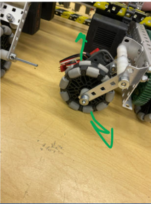
My robot is a 4 wheeled tank drive design that incorporates two perpendicular dead wheels and an IMU in the center. A key to any odometry system is understanding the kinematics of what your tracking. For instance a car with ackerman steering operates very differently to a tank drive vehicle resulting in very different kinematics for their motion. Pictured below are an example of tracking wheels.

The following image shows some of the kinematics for a two wheel differential drive robot. The design of tank drive robot I used is nearly identical kinematically since it two is a differential drive and the only major difference is the turning due to the 4 wheels. The y is tracked by the frontward motion and x is tracking the sideways motion. A robot the is able to strafe has more kinematics to account for. However, the tank drive cannot drive sideways but it can drift which the reason x needs to be accounted for but accuracy is not the most paramount thing.


Logic
- Store sensor values
- Calculate the local change
- Update values
- Convert to global The primary math behind the kinematics was gathered from 5225 Pi-lons document on the topic. The only changes made were when converting to global coordinates. While they suggest one of many methods that simplifies complex multidimensional calculus such as polar coordinates this would not function with local coordinate axis I assumed. So I used the following equation to get the change in global coordinates. \(\Delta Y_{G}=\Delta X_{L} \sin(\theta)+ \Delta Y_{L} \cos(\theta)\) \(\DeltaX_{G}=\Delta X_{L} \cos(\theta)- Delta Y_{L} \sin(\theta)\) This equation was before I aquired knowledge of how to do this in simpler ways with more calculus principles so instead I simplified a matrix to describe the rotation of a coordinate plane.
PID
As mentioned in my PID project I eventually encorporated PID’s to control the drivetrain based upon this coordinate system. My system uses radians and rotational wheel degrees traveled internally but did take more human inputs like inches. However, I learned after this project that even debugging information should be human readable. Originally my code outputed debugging information in the internal units since I learned to read these units but for other people this is not useful. Safe to say this was a valuable lesson I strive to remember in future projects.
The distance driven can be calculated as vectors which use polar or parametric equations to correctly convert from a local coordinate to global coordinate. The use of local coordinates is done to simplify math by starting at origin at each time step and accounting for the offset later in global coordinates. While this simplification especially with Vex sensors can introduce some inaccuracy it is largely neglagable because the robot is only expected to be used in a 12 x 12 arena.
For my robot I opted to use an inertial sensor rather than a third tracking wheel. With vex sensors the third wheel was used before an accurate inertial sensor got released but even then if properly done it can be just as accurate. An inertial sensor however is smaller than the third wheel and allowed us to worry less about the implementation of these wheels. This change does change the math because we no longer need to calculate the angle or keep track of it other than through the sensor output.
Graphics
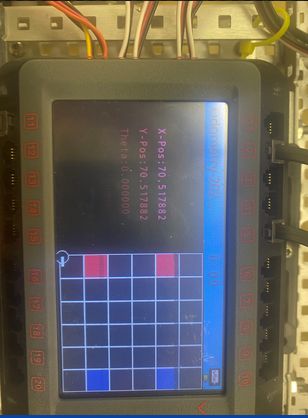
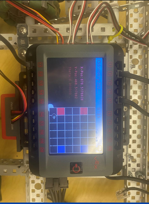
I utilized a graphic for debugging that created the standard Vex arena on the screen. It moved a small circular sprite with the correct movements the odometry was tracking to help debugging internal vs external expectations. Typically this screen was kept off since it was just for my initial development debugging and not relying on any algorithms.


Code
The following code is my eventual object oriented refactor of the odometry code. The drawing function is specifically for the graphical screen mentioned above.
void Odometry::draw() {

    int textadjustvalue = 55;
    int rowadjust = 39;
    double fieldscale=1.66548042705;
    //Sets graphical things for our display
    Brain.Screen.setPenWidth( 1 );
    vex::color redtile = vex::color( 210, 31, 60 );
    vex::color bluetile = vex::color( 14, 77, 146 );
    vex::color graytile = vex::color( 49, 51, 53 );
    Brain.Screen.setFillColor(vex::color( 0, 0, 0 ));
    Brain.Screen.setFont(vex::fontType::mono20);
    Brain.Screen.setPenColor( vex::color( 222, 49, 99 ) );

    //Displays all the field tiles, text of odom values, and a dot symbolizing the robot
    Brain.Screen.printAt(40,20 + textadjustvalue, "X-Pos:%f",xPosGlobal);
    Brain.Screen.setPenColor( vex::color( 191, 10, 48 ) );
    Brain.Screen.printAt(40,50 + textadjustvalue, "Y-Pos:%f",yPosGlobal);
    Brain.Screen.setPenColor( vex::color( 141, 2, 31 ) );
    Brain.Screen.printAt(40,80 + textadjustvalue, "Theta:%f",absoluteAngle);
    Brain.Screen.setPenColor( vex::color( 83, 2, 1 ) );
    Brain.Screen.printAt(40,110 + textadjustvalue, "Angle:%f",TurnGyroSmart.rotation(deg));
    Brain.Screen.setPenColor( vex::color( 255, 255, 255 ) );
    Brain.Screen.setFillColor( graytile );
    Brain.Screen.drawRectangle( 245, 2, 234, 234 );
    Brain.Screen.drawRectangle( 245, 2, 39, 39 );
    Brain.Screen.drawRectangle( 245, 80, 39, 39 );
    Brain.Screen.drawRectangle( 245, 119, 39, 39 );
    Brain.Screen.drawRectangle( 245, 197, 39, 39 );
    Brain.Screen.drawRectangle( 245+rowadjust, 2, 39, 39 );
    Brain.Screen.drawRectangle( 245+rowadjust, 41, 39, 39 );
    Brain.Screen.drawRectangle( 245+rowadjust, 80, 39, 39 );
    Brain.Screen.drawRectangle( 245+rowadjust, 119, 39, 39 );
    Brain.Screen.drawRectangle( 245+rowadjust, 158, 39, 39 );
    Brain.Screen.drawRectangle( 245+rowadjust, 197, 39, 39 );
    Brain.Screen.drawRectangle( 245+(2*rowadjust), 2, 39, 39 );
    Brain.Screen.drawRectangle( 245+(2*rowadjust), 41, 39, 39 );
    Brain.Screen.drawRectangle( 245+(2*rowadjust), 80, 39, 39 );
    Brain.Screen.drawRectangle( 245+(2*rowadjust), 119, 39, 39 );
    Brain.Screen.drawRectangle( 245+(2*rowadjust), 158, 39, 39 );
    Brain.Screen.drawRectangle( 245+(2*rowadjust), 197, 39, 39 );
    Brain.Screen.drawRectangle( 245+(3*rowadjust), 2, 39, 39 );
    Brain.Screen.drawRectangle( 245+(3*rowadjust), 41, 39, 39 );
    Brain.Screen.drawRectangle( 245+(3*rowadjust), 80, 39, 39 );
    Brain.Screen.drawRectangle( 245+(3*rowadjust), 119, 39, 39 );
    Brain.Screen.drawRectangle( 245+(3*rowadjust), 158, 39, 39 );
    Brain.Screen.drawRectangle( 245+(3*rowadjust), 197, 39, 39 );
    Brain.Screen.drawRectangle( 245+(4*rowadjust), 2, 39, 39 );
    Brain.Screen.drawRectangle( 245+(4*rowadjust), 41, 39, 39 );
    Brain.Screen.drawRectangle( 245+(4*rowadjust), 80, 39, 39 );
    Brain.Screen.drawRectangle( 245+(4*rowadjust), 119, 39, 39 );
    Brain.Screen.drawRectangle( 245+(4*rowadjust), 158, 39, 39 );
    Brain.Screen.drawRectangle( 245+(4*rowadjust), 197, 39, 39 );
    Brain.Screen.drawRectangle( 245+(5*rowadjust), 2, 39, 39 );
    Brain.Screen.drawRectangle( 245+(5*rowadjust), 80, 39, 39 );
    Brain.Screen.drawRectangle( 245+(5*rowadjust), 119, 39, 39 );
    Brain.Screen.drawRectangle( 245+(5*rowadjust), 197, 39, 39 );
    Brain.Screen.setFillColor( redtile );
    Brain.Screen.drawRectangle( 245, 158, 39, 39 );
    Brain.Screen.drawRectangle( 245, 41, 39, 39 );
    Brain.Screen.setFillColor( bluetile );
    Brain.Screen.drawRectangle( 245+(5*rowadjust), 41, 39, 39 );
    Brain.Screen.drawRectangle( 245+(5*rowadjust), 158, 39, 39 );
    Brain.Screen.setPenColor( vex::color( 255,255,255));
    Brain.Screen.setFillColor( vex::color(0,0,0) );

    //This draws the robot body for position and arm for angle
    double yfieldvalue = ((-yPosGlobal*M_PI*wheelDiameter)/360*fieldscale)+245-10;
    double xfieldvalue = ((xPosGlobal*M_PI*wheelDiameter)/360*fieldscale)+245;
    Brain.Screen.drawCircle(xfieldvalue, yfieldvalue, 10 );
    Brain.Screen.setPenWidth( 4 );
    //Line angle calculation:
    //x1 and y1 are the robot's coordinates, which in our case is xfieldvalue and yfieldvalue
    //angle is the angle the robot is facing, which in our case is Theta
    //(x1,y1, x1 + line_length*cos(angle),y1 + line_length*sin(angle)) = (x1,y1,x2,y2)
    Brain.Screen.drawLine(xfieldvalue, yfieldvalue, xfieldvalue+cos(absoluteAngle)*15, yfieldvalue+ sin(absoluteAngle) *15);
}
int Odometry::trackPosition(){
    absoluteAngle = ConvertToRadians(-TurnGyroSmart.rotation());
    startAngle = M_PI/2;
    //printf("posx %f",xPosGlobal);
    startPosX=(xIn*360)/(M_PI*wheelDiameter);
    //printf("startx %f\n",startPosX);
    startPosY = (yIn*360)/(M_PI*wheelDiameter);
    yPosGlobal = startPosY;
    xPosGlobal = startPosX;
    sTrackDistance = (sDistanceInput*360)/(M_PI*wheelDiameter);
    rTrackDistance = (rDistanceInput*360)/(M_PI*wheelDiameter);
    while(1){
        //change in encoder value between iterations
        deltaR = (Right.position(deg)-prevR);
        deltaS = (Back.position(deg)- prevS);
        //printf("right pos%f\n",Right.position(deg));

        //previous encoder value
        prevR = Right.position(deg);
        prevS = Back.position(deg);

        //total change in encoder over all time
        totalDeltaDistR += deltaR;

        //the current heading of the robot converted to radians
        absoluteAngle=ConvertToRadians(-TurnGyroSmart.rotation(deg));


        //the change in theta between iterations
        deltaTheta = absoluteAngle - prevTheta;
        //previous angle
        prevTheta = absoluteAngle;

        //if the robot's change in theta exists then we moved in 2 axis not just 1
        if ((deltaTheta !=0)) {
            halfAngle = deltaTheta/2;
            r = deltaR/deltaTheta;
            r2 = deltaS/deltaTheta;
            //The change in pose in this frame
            deltaXLocal = 2*sin(halfAngle) *(r2-sTrackDistance);
            deltaYLocal = 2*sin(halfAngle) * (r-rTrackDistance);

        //if the angle didn't change then we only moved in one direction
        } else {
            //This is not likely to happen because drift exists
            deltaXLocal = (deltaS);
            deltaYLocal = (deltaR);
            halfAngle = 0;
        }
        avgTheta=absoluteAngle-halfAngle;
        //the change in theta of the coordinates
        //Converting the local pose change to a global one
        deltaYGlobal = (deltaXLocal) *cos(avgTheta) + (deltaYLocal) * sin(avgTheta);
        deltaXGlobal = (deltaYLocal) * cos(avgTheta) - (deltaXLocal) * sin(avgTheta);

        //adds the change to the original coordinates yielding new coordinates
        xPosGlobal += (deltaXGlobal);
        yPosGlobal += (deltaYGlobal);
        printf("Posx: %f\n", xPosGlobal);
        printf("Posy: %f\n", yPosGlobal);
        //draws coordinate grid on brain
        draw();

        task::sleep(10);
    }
    return 1;
}

double Odometry::getXPosGlobal(){
    return xPosGlobal;
}
double Odometry::getYPosGlobal(){
    return yPosGlobal;
}
double Odometry::getDeltaXG(){
    return deltaXGlobal;
}
double Odometry::getDeltaYG(){
    return deltaYGlobal;
}
double Odometry::getAbsoluteAngle(){
    return absoluteAngle;
}
double Odometry::getPrevTheta(){
    return prevTheta;
}
void Odometry::setXIn(double i){
    xIn=i;
}
void Odometry::setYIn(double i){
    yIn=i;
}
void Odometry::setAng(double a){
    startAngle=a;
}
void Odometry::setSDistInput(double i){
    sDistanceInput=i;
}
void Odometry::setRDistInput(double i){
    rDistanceInput=i;
}

//to use Odometry odom;
//task odom.trackposition;
I will note that the way this runs in the Vex V5 system was you needed to create a task that will run this function in the background constantly so that it could run below blocking functions that may rely on accuracy in the location data returned from it.